electrical
This page describes the electrical hardware that we used for each user interaction.
Schematic
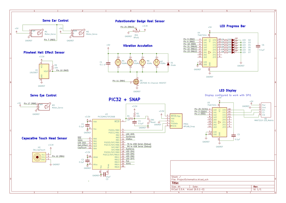
All hardware for this project is controlled by a single PIC32MX170F256B microcontroller and powered by a 3.3V breadboard power supply and a 5V external power supply.
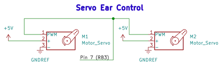
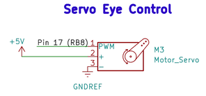
Ears and eyes: Servo Circuits
Three servos are used in this project: each ear is controlled by a 3 kg-cm servo, while one 1.4 kg-cm servo controls both eyes. All servos are controlled directly by the PIC, and draw power directly from the external 5V power supply.
|
|
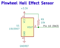
The pinwheel: Hall Effect sensor
A latching hall effect sensor is used to detect the rotation of the pinwheel by measuring changes in the magnetic field. Every time the hall effect sensor detects change in polarity, it sends a high signal to the PIC. A 10kΩ pull-up resistor is used to ensure the input signal reaches a sufficiently high voltage to register as a high input on the PIC.
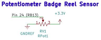
Stretching: The potentiometeR
A single rotary potentiometer is used to generate an analog signal for how far the user has stretched the ball.
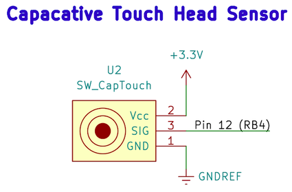
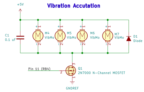
Haptic Feedback: Capacitive button and Vibration Motor
A capacitive button is used both to turn on Baby Yoda and to initialize the haptic feedback response. Four vibration motors are placed in parallel with a diode and bypass capacitor, and controlled by a 2N7000 n-channel MOSFET. Experimentally measured values for the resistance of the vibration motors found the motors are small enough that the maximum current they draw is substantially less than the maximum drain current for the 2N7000. The diode was added to protect the rest of the circuit from the back EMF generated when the motors are turned off. Since the output high of the PIC is 3.3V, a pull-up resistor is not needed for the gate-to-source voltage to exceed the required 2.1V needed for the 2N7000 to transition to the on state.
|
|
The LightsabeR
The light saber contains six diffused 10mm LEDs, which are plugged into a 74ACT244 octal buffer. Each pin on the buffer is controlled directly by the PIC. The buffer allows the LEDs to run off a 5V power supply and draw current from the power supply instead of the PIC.
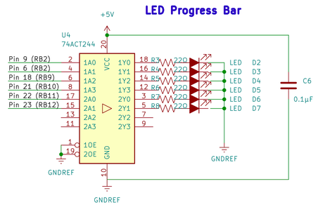
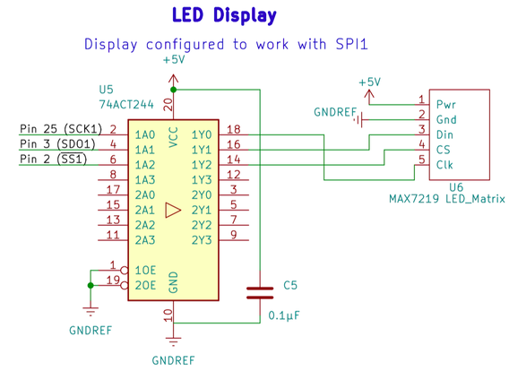
THe LED Display
The LED display matrix is connected to a separate 74ACT244 from the lightsaber LEDs. The buffer is controlled directly by the PIC.